
Creating a Test Plan - FCC WiFi 6G
The FCC WiFi 6G option is used for FCC / IC (ISED) certification testing of 6 GHz RLAN products (Wi-Fi 6E / Wi-Fi 7, etc.).
Basic Settings
The figure below takes Wi-Fi 6E as an example.
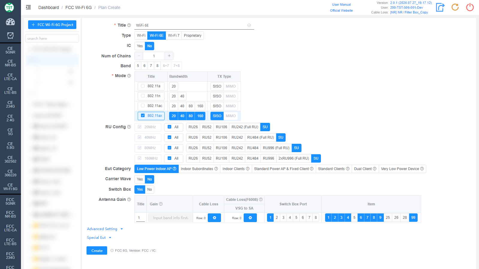
Title: Test plan name, entered by the user.
Type: Technical category. Select the corresponding Wi-Fi standard, or Proprietary for self-defined products:
Wi-Fi: All 802.11 modes (a / n / ac / ax / be).
Wi-Fi 6E: 802.11a / n / ac / ax.
Wi-Fi 7: 802.11be.
Proprietary: Self-defined product.
IC: Whether to test according to Canadian IC (ISED) requirements as well, default No.
Num of Chains: Number of transmit chains (antennas).
Band: 6 GHz sub-bands supported by the product, multi-select: 5 / 6 / 7 / 8 (U-NII-5 ~ U-NII-8) and cross-band combinations 6+7 / 7+8.
Mode: Modes supported by the product (required). After checking a mode, select the Bandwidth (20 / 40 / 80 / 160 MHz...) and TX Type (SISO / MIMO).
RU Config: RU (Resource Unit) configurations supported by 802.11ax / be devices, selected per bandwidth. Full RU of each bandwidth is mandatory; select other RU configurations according to the product's actual support; SU (Single User) can be checked separately.
Eut Category: 6 GHz equipment category, corresponding to the FCC equipment class codes:
Low Power Indoor AP (6ID)
Indoor Subordinates (6PP)
Indoor Clients (6XD)
Standard Power AP & Fixed Client (6SD & 6FC)
Standard Clients (6FX)
Dual Client (6CD)
Very Low Power Device (6VL)
Carrier Wave: Whether the product supports carrier wave transmission. For the frequency error test.
Switch Box: Whether to use a Switch Box (RF switch).
Antenna Gain: Antenna gain and cable loss configuration:
Title / Gain: Antenna number and gain (dBi).
Cable Loss: Cable loss from the product's antenna port to the Switch Box or spectrum analyzer. How to Create Common Cable Loss.
Cable Loss(F6008): Dedicated cable loss for the F6008 CBP test.
VSG to SA: Cable loss from the signal generator to the spectrum analyzer.
Switch Box Port: Port number of the switch connected to the antenna.
Item: Test items per antenna; the numbers correspond to:
(F6001) Duty Cycle
(F6002) Bandwidth
(F6003) Maximum Conducted Output Power
(F6004) Maximum Power Spectral Density
(F6005) Unwanted Emissions In Restricted Frequency Bands
(F6006) Frequency Stability
(F6007) Emission Mask
(F6008) Contention Based Protocol (CBP)
(F6009) Dual Client Test
(F6025) Band Edge
(F6026) Spurious Emission
(F6028) Unwanted emissions in non-restriction bands
(F6099) Form731 — FCC Form 731 report
Advanced Setting and Special Eut
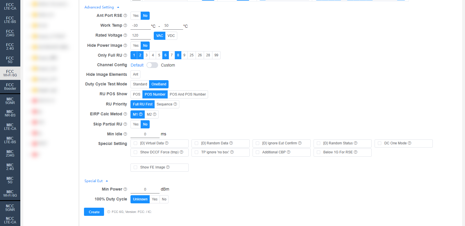
The following settings can generally be kept at their default values. Adjust them only when the test results are abnormal or there are special test requirements.
Ant Port RSE: Whether to perform the antenna port spurious test. For F6005 Unwanted Emissions In Restricted Frequency Bands. What is the Antenna Port RSE test
Work Temp: Normal operating temperature range (°C), default -30 ~ 50. Affects the frequency stability test.
Rated Voltage: Rated operating voltage, default 120 VAC. Affects the frequency stability test.
Hide Power Image: Whether to hide the power image in the report (F6005).
Only Full RU: For the checked items, only Full RU will be tested.
Channel Config: Channel configuration, Default or Custom.
Hide Image Elements: Elements to hide in report images (e.g., the Ant marker).
Duty Cycle Test Mode: Standard / OneBand.
RU POS Show: How RU positions are displayed in the report: POS / POS Number / POS And POS Number.
RU Priority: RU test priority: Full RU First or Sequence (RU26 → RU52 → RU106...).
EIRP Calc Metod: EIRP calculation method for MIMO:
M1: EIRP (MIMO) = EIRP_ANT1 + EIRP_ANT2 (converted to mW, summed, then converted back to dBm).
M2: EIRP (MIMO) = Conducted Power_MIMO + Directional Gain.
Skip Partial RU: Whether to skip Partial RU testing.
Min Idle: Minimum idle time (ms) for the duty cycle test.
Special Setting: Special settings. Options prefixed with [D] are debug options:
[D] Virtual Data / [D] Random Data / [D] Ignore Eut Confirm / [D] Random Status: Debug options.
DC One Mode: A mode only measures one duty cycle.
Show DCCF Force (tmp): Temporary option: force-enable the display of DCCF on the plots for F6003 / F6004.
TP ignore 'no box': Test Priority ignores the "no switch box" scenario. By default, fixed-frequency antennas are given the lowest priority in a "no switch box" scenario.
Additional CBP: Additional CBP for F6008 (Case5 + Minimal, ON).
Below 1G For RSE: If selected, the RSE test will be performed for frequencies below 1 GHz.
Show FE Image: If selected, the frequency error image will be displayed (default: all).
Min Power: Minimum power (dBm), 0 is auto.
100% Duty Cycle: Whether the sample's duty cycle is 100%: Unknown / Yes / No.
Corresponding software option: FCC 6G